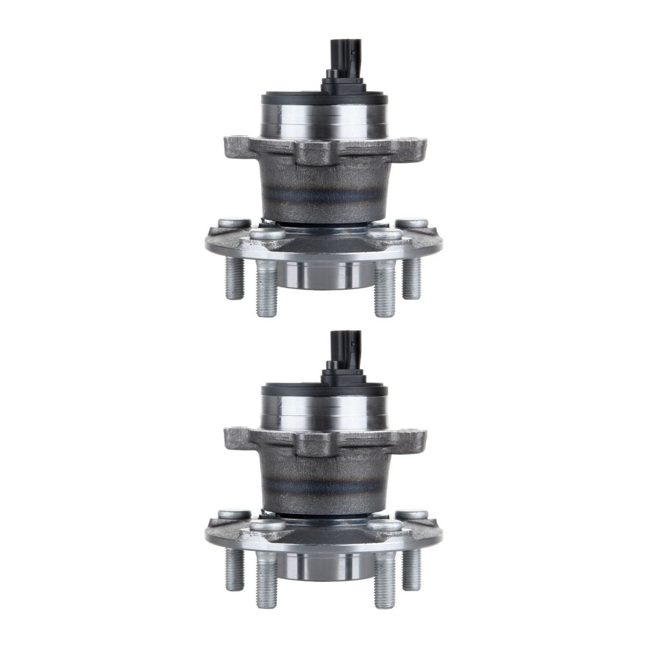
2 Sets of - For Volvo 07-13 C30 06-13 C70 05-11 S40 05-11 V50 T5 Rear Wheel Bearing
Every set can be described as following:
Product Features:
* Fits either LH (Driver Side) or RH (Passenger Side) Rear
*Fits 5 Lugs Wheels
* Wheel studs already installed
* Includes ABS with tegral Sensor
Item Description:
Direct replacement
Built to strict quality control standards
Replaces dealer part numbers:
512411,712411,WA512411,WB512411,29512411
Vehicle Fitment:
Fits Volvo C30 2007 - 2013 All Models
Fits Volvo C70 2006 - 2013 All Models
Fits Volvo S40 2005 - 2011 FWD Models
Fits Volvo V50 2005 - 2011 FWD Models
Package Include:
1 Pcs wheel hub bearing
1 Year Warranty
Exploded View:
Wheel hub and bearing
Cotter pin
Nut retainer
Wheel hub lock nut
Hub bolt
Splash guard
Steering knuckle
Removal:
Remove the bolt (1) and separate the front wheel sensor from the steering knuckle.?
Remove brake caliper torque member bolts, leaving brake hose attached, reposition the caliper aside with wire
Put alignment marks (A) on disc brake rotor and wheel hub and bearing. Remove disc brake rotor
Remove cotter pin and the nut retainer,Loosen the wheel hub lock nut from the drive shaft using power tool
Using a piece of wood and a suitable tool, tap on the lock nut to disengage the drive shaft from the wheel hub and bearing
Remove the engine side cover
Remove the lower nut and bolt from the steering knuckle,Separate transverse link from steering knuckle
Separate drive shaft from wheel hub and bearing, Reposition the drive shaft aside with wire
Remove the wheel hub and bearing bolts using power tool
Remove the splash guard and the wheel hub and bearing from the steering knuckle
NOTE:
Failure to separate the front wheel sensor from the steering knuckle may result in damage to the front wheel sensor
Pull out the front wheel sensor, being careful to turn it as little as possible
Do not pull on wheel sensorharness
Inspection after removel : Check components for deformation
y
cracks
and other damage
and boots of transverse link ball joint for cracks
axial end play,and swing torque.
Installation:
Installation is in the reverse order of the removal
Caution:
Do not reuse the wheel stud
Do not reuse the cotter pin
Place a washer (A) as shown to install the wheel studs (1) by using the tightening force of the nut (B)
Clean the mating surfaces of the joint sub-assembly and the wheel hub and bearing. Apply lubricant to the surface (A) of the joint sub-assembly
Hold the wheel hub and bearing using a suitable tool. Tighten the wheel hub lock nut
6. Since the drive shaft is assembled by press-fitting, use a torque wrench to tighten the wheel hub lock nut. Do not use a power tool
7. Too much torque causes axle noise. Too little torque causes wheel bearing looseness. Tighten the wheel hub lock nut to the specification
8. When installing a the cotter pin (1) and the nut retainer (2), securely bend the cotter pin to prevent rattles
9. Align the matching marks (A) on the disc brake rotor and on the wheel hub and bearing